

The science
The understanding of advanced MHz technology drives the elegant performance of the IPP wireless charging systems.
Get in touchTHE PHYSICS OF MEGAHERTZ FREQUENCIES
The critical relationship in the physics of inductive power is that the coupling between the transmitter and receiver coils is proportional to f2 B2, where f is the frequency and B is the magnetic flux density.
The product f.B is called the electromotive density, and the mathematics does not care whether f is low and B is large, or vice versa. However, the engineering does care... A large B and low f mean high electrical currents in the coils (needing thick copper wires), multiple turns, and ferrite cores. Each of these adds cost, weight, and performance inefficiencies.
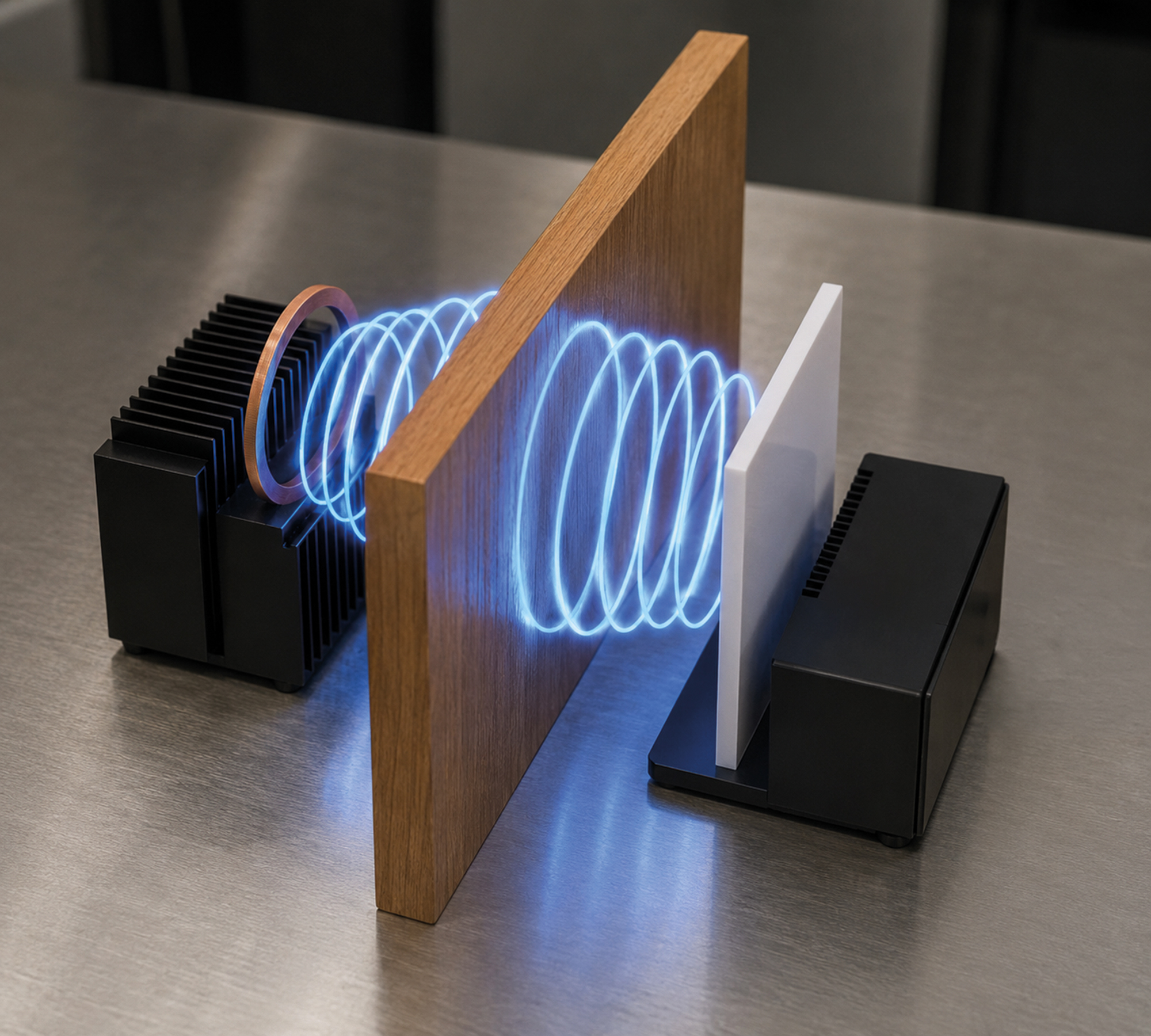
For historical legacy reasons to do with the ready availability of induction heating power electronics, other commercial wireless power systems use kHz frequencies (low f). However, we use MHz frequencies, three orders of magnitude higher, so our electrical currents are three orders of magnitude smaller to get the same performance; the thin skin depth means our copper only needs to be 50 microns (the thickness of a hair), with single turned coils (rings made from copper tube) that are air cored. These are lightweight, and resonant, with performance a magnitude better than anyone else in the world.
We can use 3D printed plastic and electroplating for the rings, super light-weight, configuring them to fit awkward geometries; we don't heat surrounding metals (again, advantage of thin skin depth); or pot in epoxy resin for deep ocean or ATEX applications. It took us 10 years to develop the inverters, rings, and rectifier, but the effort is worth the performance gains.
IPP Technology vs. Alternative Solutions
|
IPP Wireless
(MHz frequency) |
Conventional Wireless
(kHz frequency) |
Physical Contacts
(Pins and Plates) |
Electro-Mechanical
(Battery Swap or Plug-in Connector) |
|
|---|---|---|---|---|
| Contact required | None (air gap) | None (air gap) | Yes (metal contact) | Yes (physical interface) |
| Typical power capability | High (kilowatt-level) | High (kilowatt-level) | High (kilowatt-level) | High (kilowatt-level) |
| Alignment tolerance | High (decimetre-scale+) | Low (centimetre-scale) | Very Low (precise mating for pins) | Very low (precise mechanical fit) |
| Power Transfer Distance | High (decimetre-scale+) | Low (centimetre-scale) | None (contact required) | None (contact required) |
| Moving parts | None / minimal (solid-state / cooling fans) | None / minimal (solid-state / cooling fans) | None / minimal (springs) | Multiple (actuators) |
| Environmental robustness | High (sealed surfaces) | High (sealed surfaces) | Low (corrosion risk; dirt, water, ice ingress) | Low (corrosion risk; dirt, water, ice ingress) |
| Maintenance burden | Low (some inspection) | Low (some inspection) | High (cleaning, replacement) | Very High (regular servicing) |
| Parasitic Mass (on drone) | Medium (3D printed receiver + rectifier >200 g / kW) | High (thick copper coils, ferrite cores circa 1 kg / kW) | Low | Not applicable |
| Heat transfer (to surrounding metallic objects) | Low | High | Not applicable | Not applicable |
| Resilient to FOD (foreign object debris) | High (no FOD detection required) | Low (FOD detection required) | Low (FOD detection required) | Low (FOD detection required) |
| Autonomy readiness | High (forgiving landing) | Moderate (repeatable alignment) | Moderate (tight tolerances) | Low (complex automation) |